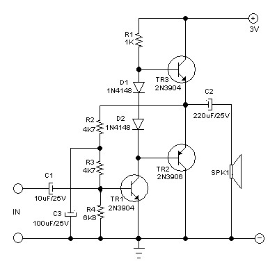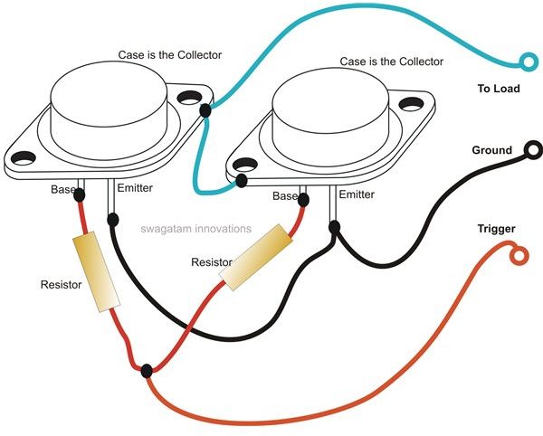


You need to make sure you have a beefy transistor to supply base current as soon as possible. My additional comments are you have to remember temperature degradation and the non ideal world. Ordered some 30 amp automotive fuses off ebay and some new 2n3055 transistors. I also don't have a diode going from the emitter back to the collector, I'm not sure why they put this here? Should I also have a resistor for each of the bases of these pass transistors to help with load sharing? Before blowing they both were getting a tiny bit warm with a 2 amp load at 12v after about 2 minute but not hot by any means.Īny help would be appreciated thanks in advance To give you an idea of my schematic it looks like the one in this link -Įxcept for the control circuitry is an lm317 instead of the lm723 I.C shown in this schematic. I thought these things had overload protection? Is it possible that while tightening the chuck on the drill (motor in drill only slightly moving while holding the chuck key with hand to put a new drill bit in) That I drew more than 30 amps and blew them both?
#2n3055 pass transistor schematic full
They were only getting slightly warm when I noticed the output voltage was giving a full 30v's instead of the regulated setting I had at 14v. It worked for a while so I started drilling some holes in the power supply case (timber so no chance of a short).
#2n3055 pass transistor schematic portable
I tested it out last night with a little portable drill that I butchered to have 12v leads comming off for portable work requirements.

These 2n3055's are rated for 15 amps each and they're paralleled so I should theoretically get 30 amp handling capacity. I don't need any more supplies and have plenty in all applications, just curious about this unit and would like to add the docs to my sencore repository.I'm a little stumped as I just put my power supply together which long story short consists of an lm317 driving two 2n3055 pass transistors. I have seen an accessory for these power supplies that further took the variable, current limited output and created a separate, 3 output, low current, multi voltage power supply suitable for powering boards requiring multiple supply sources or clamping circuits, especially nice when you had direct coupled stages.ĭoes anyone have a copy of the manual? All I have is the schematic as shown above. In older, pre-transistorized regulation schemes for high current, light bulb ballasts and a swinging choke often were employed to give some degree of regulation. I don't get how they can consider the first two positions regulated. The 6V and 12V high current output from what I can see is wild from the bridge to a 10Kuf cap with only the fuse and current shunt in line. From the schematic, only the 2A position appears to be regulated in the 15V & 30V ranges with the current limiting ranges. The variable 2A high filtered, regulated position on the third position. It shows as Walt indicates that there is a 12/10A and 6V/20A position, but says "regulated supply and charger". I took a look at some Fleabay pictures of these supplies.


 0 kommentar(er)
